

The OSI Reference Model The Layered Communication Hierarchical Network Model
With the advent of computer networks, the need for a common standard to integrate the networks of different manufacturers emerged. BEfore, companies developed proprietary network systems and offered them as packaged solutions, leading to expensive and closed systems. Despite functioning well internally, these systems faced challenges or impossibilities in communicating with external networks. For instance, IbM operating systems could communicate among themselves using IBM network devices. However, communicating with other networks posed difficulties. Recognizing the demand-supply gap in network systems and the pressure from hardware manufacturers in the network market, it became apparent that a standard model was necessary for the functions of network systems.
For that reason,, the International Organization for Standardization (ISO) introduced the OSI Reference Model in 1978 as a standard for computer networks. Originally presented in 1978, this standard was restructured in 1984 and released as the OSI (Open System Interconnection) reference model. Widely accepted, the model has served as a guide for network processes.
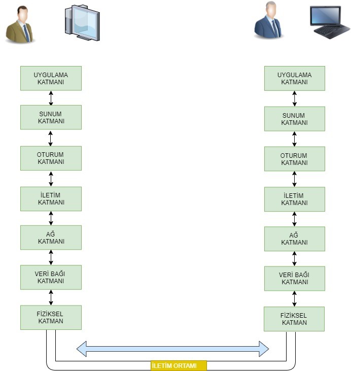
The OSI Model categorizes communication processes in computer networks, from the communication medium (wired or wireless) to the end-user, into 7 layers:
-Physical Layer
-DataLink Layer
-Network Layer
-Transport Layer
-Session Layer
-Presentation Layer
-Application Layer
The OSI Reference Model
Is a standardized model for ensuring data communication. This hierarchical network model facilitates the design and management of computer networks, as data passes through all these layers according to the OSI model. That is why, a network specialist needs a deep understanding of this model to analyse and resolve problems efficiently in the network system. Each layer has specific tasks, protocols operating in each layer, and their respective functions.
What is Protocol?
A protocol is a set of rules established to ensure the operation and avoidance of errors in a process. In computer netwotrks, the term protocol defines how two hardware or software entities should communicate based on predefined rules. Even daily tasks like sending an email or a whatsapp message involve numerous protocols in the background. For instance, the File Transfer Protocol (FTP) identifies how two software running on separate computers exchange data. The Transmission Control Protocol (TCP) manages the fragmentation of data on the sending system and its reassembly on the receiving system. The Internet Protocol (IP) ensures the correct routing of data through various routers to reach the destination. The network card defines how data should be transmitted as eletrical signals.
The layers and functions of the OSI Reference Model can be defined as follows:
1- Physical Layer defines how data particles (bits) are transmitted in transmission mediums such as cables, fiber, or air. On the sending side, the Physical Layer transmits 1s and 0s into a form understandable by the transmission medium (such as electrical signals, radio signals, or light). On the receiving side, the Physical layer reads these signals from the transmission medium and converts them back into 1s and 0s. For different manufacturers' network hardware to communicate seamlessly with each other, the outgoing and incoming data bits must represent the same information for different brand hardware. In other words, it is necessary to establish specific standards and use the same protocols. Some of the standards used include:
- EIA/TIA-232
- EIA/TIA-449
- V.24
- RJ45
- FDDI
- V.35
- Ethernet
- NRZ
- B8ZS
- GBIC/SFP
2- DataLink Layer: TThis layer ensures that the data sent from the source is transformed into frames and delivered to the destination address. It consists of two sub-layers: Media Access Control (MAC) and Logical Link Control (LLC). The MAC sub-layer utilizes a unique 48-bit MAC address present in each network card to facilitate accurate communication by using source and destination MAC addresses in the data packet. The LLC sub-layer takes on the transition task for the layer above, creating logical ports called Service Access Points (SAPs) to facilitate communication between the two layers. In this layer, the CRC error-checking protocol and CSMA/CD collision protocol are used to ensure error and collision control for the transmitted data.
- IEEE 802.3/802.2
- HDLC
- Frame Relay
- PPP
- FDDI
- ATM
- CSMA/CD
- CSMA/CA
3- Network Layer: this layer ensures that data reaches its destination from the source by utilizing the network address (IP address). In this layer, the packet is named after the data, with both source and destination IP addresses included. The IP packet contains information such as the total size of the packet, Time-to-Live (TTL), service type, version, error checking, along with the addreses. Routers and routing algorithms that guide data in the network operate at this layer. Some of the protocols used in this layer include:
- IP
- IPX
- AppleTalk DDP
- ARP
- RARP
- ICMP
- RIP
- EIGRP
4- Transport Layer: This layer facilitates the transmission of data from the source to the destination by breaking down the data into segments. Additionally, it performs error correction based on the results of error-checking processes carried out by other layers. Flow control between the source and destination is managed at this layer. Two significant protocols in this layer are TCP (Transmission Control Protocol) and UDP (User Datagram Protocol), each serving distinct purposes and use cases. Port addresses, uniquely assigned for different applications, are vital components of this layer. Important protocols used in this layer include:
- TCP
- UDP
- SPX
- RTP
- SIP
- H.323
5- Session Layer: This layer initiates, manages, and terminates communication between the source and destination. Each application used on the client, such as email, web browser, or FTP, establishes a separate session to prevent the mixing of data between applications. The protocols and services operating in this layer are provided below:
- Sockets
- RPC
- Netbios
- NFS
- AppleTalk ASP
- SQL
6- Presentation Layer: The meaningful interpretation of shared data between computers in a network is facilitated by this layer. In order for the shared information to be readable by PCs, the data needs to be transformed into a common format. The importance of this function becomes salient when considering that computers involved in sharing may be managed by different software. Thus, it becomes possible for different programs to utilize each other's data. One of the most crucial tasks of the Presentation Layer is the ability to transmit shareddata to the receiving computer in an encrypted form. In fact, the Presentation Layer is not directly related to the network but is rather associated with software. In today's context, operating systems cannot read many formats that have been created. This means that if our operating system does not support the format of data received from another user, that information is meaningless to us. For instance, to watch videos shared in the divx format on the internet today, it is essential to have supporting codec programs on computers. During the process of opening a divx file on one computer from another, the Presentation Layer is not directly involved; what is meant here is the use of software and programs capable of decoding the same format. Some of the formats we use include the following:
- GIF
- DIVX
- DOC
- ASCII
- EBCDIC
- TIFF
- JPEG
- PICT
- MPEG
- MIDI
7- Application Layer: This layer provides tools for users and programs to utilise the network. As the final layer, the application layer does not provide any services to the other layers. It creates network services for running applications. Microsoft APIs operate at this layer. A programmer using Microsoft APIs can, for example, retrieve a ready made tool from the API when accessing a network driver and use it in their own program without dealing with the various processes happening in the lower layers. Another example is HTTP. HTTP is not a program but a protocol string of rules. According to this protocol, an Internet Explorer, functioning based on the same protocol, connects to other web servers. Additionally, this layer determines whether the computer it will communicate with is ready for communication and synchronizes the communication. Some of the applications and protocols used in this layer include:
- Telnet
- HTTP
- Web browser
- NFS
- Facebook
- FTP
- SNnMP
- SMTP gateway
To illustrate the tasks of each layer, let's consider an example: a user (A) wants to send a file to a server (B) using FTP. The application layer's FTP program is the interface point on User A's computer. The file is transmitted to the computer through this layer. The file to be sent is packaged in the format requested by the FTP protocol at the presentation layer. The session layer initiates a session for this communication. The transport layer divides the file into segments, adding relevant data such as port numbers, control variables, etc., creating Protocol Data Units (PDUs). Each segment of the segmented file is then sent to the network layer, which adds its own PDU containing source and destination IP addresses and other control variables for each piece. The data link layer, in turn, adds its PDU containing source and destination MAC address information and other control parameters, sending it to the physical layer. The physical layer transmits the entire package, now a string of 1s and 0s, to the connected communication medium as electrical signals, radio signals, or light. After switching and routing processes, the string of 1s and 0s reaching the destination undergoes reverse operations to be recorded again by the FTP program in the application layer.
In addition to the OSI reference Model, another widely used model is the TCP/IP model. This model is a simplified version of the OSI Reference Model, consisting of four layers after merging some layers of the OSI model. A comparison between the OSI Reference Model and the TCP/IP model is outlined below.
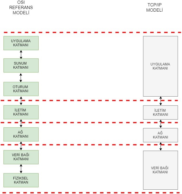
The Hierarchical OSI Reference Model and TCP/IP Model
HIERARCHICAL NETWORK MODEL
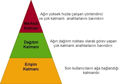
Information technology experts employ the hierarchical network model to simplify the design and management of networks. For problem resolution and the healthy functioning of the established system, there should be a common language between those building the network and those using it. The increasing complexity of applications with advancing technology leads IT professionals towards faster and more applicable routing and switching techniqus. The success of all these developments depends on the error-free operation of the network environment required by end-users. Establishing this structure is achieved through the seamless operation of the client-server architecture. In today's context, this is accomplished with a three-layered hierarchical model, consisting of the following layers:
- Access Layer
- Distribution Layer
- Core Layer
Hierarchical Network Model
Access Layer: The Access Layer is the point where end-users connect to the network. It comprises a group of end-users and their resources. Standard switches are typically used in this layer.
Distribution Layer: This layer is responsible for the distribution from the core layer to the access layer. It controls where and how the access layer can reach. Multilayer switches are commonly used in this layer.
Core Layer: The Core Layer can be described as the backbone of the network, serving as the central pooint for all clients and resources. This layer accommodates high-speed routers, multilayer switches, and security devices.